Wednesday, January 24, 2018

Front Disc Brake Conversion - Part 2

The title of this post should be 'Hubs, Studs and Rotors'. As I always like to say, 'the devil is in the details'. What appears easy on the surface, rarely is - and this seems to apply to front disc conversions as well. 

So let's set the stage. We are converting a 68 Mustang with manual drum brakes to power disc brakes. We will be utilizing an adapter kit from Steve's Mustang and donor parts from a '94-04 Mustang Cobra. Sven already has written a superb in-depth article on how to do this correctly so I'm not going to replicate it here:

                               http://1970boss302.blogspot.com/search?q=disc+brake

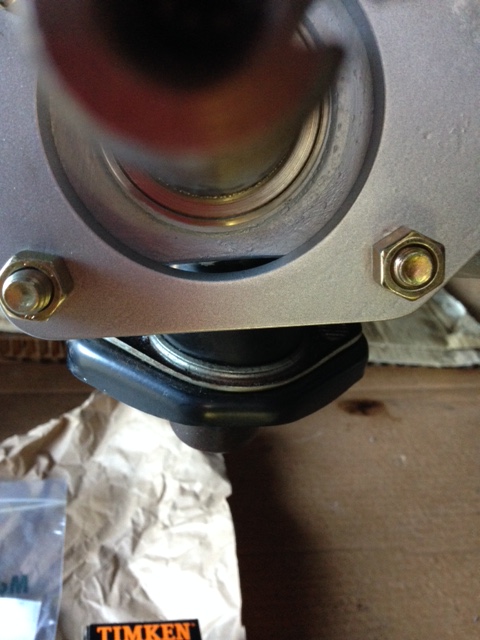
The instructions that come with Steve's kit are clear and straightforward, but I want to expand on a few areas. Let's start with separating the brake drum from the hub. A really important detail to note here is that the brake drums are secured to the hubs by 'swedging' the wheel studs. Basically, after installing the drum over the shoulder of the wheel stud at the factory, a pneumatic tool expands the OD of the wheel stud, effectively locking the brake drum to the hub. You can see the marks left on the wheel stud by the swedging process below. 


So why is this important to know? Based on a number of posts I read in various forums, if you try and press these swedged studs out of the hub, in order to separate the drum from the hub, the expanded OD of the shoulder will over-expand the knurled hole in the hub as it passes through the hub flange. If you reinstall an OEM stud back into this enlarged hole, there's the potential it will spin in the hole when it comes time to torque the lugs nuts as there won't be enough material left for the new knurls to get a good 'bite'. I can't confirm this, but given the number of posts on Jeep and Model T forums on this issue, I chose to err on the safe side and remove the drum from the hub per Steve's instructions. And that is to simply place a plate across the top of the outer bearing retainer and press the hub from the drum, rather than the studs from the hub. 

But let's say you do want to replace the original studs with new OEM ones. You still need to get past the swedged stud problem. Well a company called Goodson makes the exact tool you are looking for, and here it is. It's a bit pricey, but after reading some of the backyard solutions to the problem that involved all manner of hacking, beating, grinding and overall general mayhem, this seems like the gentleman's solution to the problem.


OK then, let's get back to SusieQ. In my specific case, I actually wanted to save the original studs, so I had no need for the $92.99 tool above. And the reason I wanted to save the original studs was due to my wheel choice. As you recall, I'm going to run 2005 Mustang GT 17" rims. In order to do that, I need to run ( yep, you know it's coming) 1" wheel spacers. I feel as much shame about it as you do.  But I love the rims and they are exactly the look I want for the car. Yes, I know, I should just run a rim with the correct offset and do the job right. In my defense, all projects are ultimately a series of compromises - this is mine. 

And this is where 'the devil is in the details' raises its ugly head. Since Cobra rotors are used with a shoulderless wheel stud, they will not fit over an original OEM shouldered, brake drum stud. Worse, they really won't fit over a swedged, shouldered, brake drum stud. The stud holes in my OEM Cobra rotors were roughly .570" ID. An unswedged stud shoulder measures .605" OD, a swedged one almost .617". So it is a no-go by quite a bit. When I first discovered this problem, I thought I would be clever and just order a new set of OEM shouldered studs that hadn't been swedged - only to discover that even the un-swedged ones have too large an OD. As a heads-up here, Steve does sell a wheel stud just for this issue    (#610-368). They are non-shouldered, longer for the thicker flanges of modern rims and even have a larger OD knurled section for pressing into hub flanges that have had previously installed studs. Only thing is, I can't use them. The longer length causes them to protrude out past the outer surface of the wheel spacer. This would prevent the rim from sitting flush against the mating surface of the spacer. Fudge...


OEM brake drum wheel stud - C3AZ-1107-A (1 11/16"L)
Steve's Mustang - shoulderless wheel stud (2 3/16"L)


I pondered this problem for a few days. Thought about turning down the OD of the new brake drum studs I had already purchased and installing them. That would work. A pain, but at least a solution. Would need to buy the $95 de-swedging tool from Goodson though. I could live with that. But then while driving home from work one night the simple answer came to me. I currently have a .617" OD swedged stud - all I need to do is open the rotor holes up to .625" and problem solved. Next morning I threw the rotor up in the mill, indexed it in, and passed a brand new 5/8" ream through all 5 holes. As a nice by-product, the shoulder clearance is nearly spot on and the rotors go on with a comforting clunk. A heads-up here is that you need to remove the small burrs left from the swedging process. All it takes it a small fine hand file and a little patience. Downside? Yes, I now have a non-standard rotor. This could potentially cause me a head ache down the road, and anyone else who ends up with the car after I'm finished with it. Upside? I can still install the turned-down OEM studs down the road, but for now, it's forward and onward.

13" Cobra rotor in the mill w/ 5/8" ream
One last issue to note - and it's an important one. As Steve spells out in the instructions, the OD of the early Mustang hub is larger than the ID of the rear face of the Cobra rotor. It's not by much, but enough that the rotor won't sit flush on the hub face. So you need to remove some material from the OD of the hub so the rotor sits flush. Apparently they used different vendors for these hubs so there's no single, standard OD. In my case, I seemed to have an extra large one and needed to take .075" off the diameter to get a nice flush fit. I added a 45 deg chamfer for extra insurance. 

rotor chucked in lathe - plugged to keep shavings out
close-up of turned diameter and 45 deg, 1/16"wide chamfer


In Part 3 we'll finish up with some polishing and powder coating. Stay tuned!


Monday, January 22, 2018

Front Disc Brake Conversion - Part 1

Like Sven, I was busy in 2017 with things other than our Mustangs. And like Sven, I can't say much about what I was working on either. Let's just say it involved (2) Ford Raptors and a whole lot of fun. I'm always amazed they actually pay me to do what I do!

But back to SusieQ. As I mentioned in the previous post, while in Australia, I decided that upgrading to power disc brakes was a must. Unfortunately not as many options out there as there used to be. Settled on Mustang Steve's 1994-2004, 13" Cobra Front Disc Conversion. It's a straight forward design, the majority of it being simple, laser-cut steel plates. Three issues I think if addressed though would make for a better design:

 Issue 1: The 2 rectangular plates in the photo below could be combined into 1. I'm guessing the reason was to reduce cost by laser cutting the pieces from standard stock thicknesses, rather than CNC machining a more complicated part. The large plate is .375" thick, the smaller one .100". In order to get this same stack height from a CNC part, they would need to start with a lasercut part from .500" plate, mill it down to .475", then step it to .375" in the outer mounting areas. This lasercut method works, but I dislike the extraneous parts. I was VERY tempted to correct this - and I'm not saying I still won't.    


Issue 1: (2) Lasercut parts could be (1) machined one

 Issue 2: This one is getting nit picky, but I would like to see them expand the adapter plate perimeter a bit and match the contours of the spindle. This would be so much cleaner looking. I know, it's hid behind the rotor once it's mounted. But whether it's hidden or not, I still know it looks like this. Quite possible there's a potential interference issue with another part if you grow the perimeter so I'm not going to throw too many rocks.


Issue 2: Adapter plate doesn't follow spindle contour


Issue 3: Again, I think they are cutting costs by using a lasercut part here when a machined part would have been more appropriate. You can see the large gap between the bottom of the spindle and the ID of the adapter plate hole. Remember there are no backing plates on this set-up, so any high speed sprays of water are going to pass right through that hole - and right against the backside of the inner wheel bearing seal. They couldn't make the hole in the adapter plate any smaller or the back side of the hub wouldn't clear. I would suggest that a machined part here, with a stepped counter bore to eliminate that gap (but still allow for hub clearance, might be a better alternative. You would need to add a small drilled vertical hole in the stepped counterbore to allow water that could enter from the front side of the assembly to drain. But water coming from the front side is going to be mostly deflected by the rotor. What water that does end up inside that opening will just be "slow speed ricochets".  In their defense, I saw this same issue with both Vintage Venom and Street or Track's kits as well. So there may be a reason for this gap that I'm simply unaware of. 


Issue 3: Gap between spindle & adapter plate


Once I got everything unboxed and sorted, I took the Dewalt with the abrasive pad to the edges and got rid of all the laser cut kerfs. Cleaned everything up, sprayed on a nice heavy coat of PMB 6525 (otherwise known as BMW silver) and popped into the powder coat oven at 400 deg for 20 min. Hard to see in the photo, but a very subtle hint of metallic in this silver. I like it. Sophisticated without being snobby :)


Stay tuned for our exciting Part 2 follow-on!!!